Well Integrity Evaluation Using Wireline Techniques–From Diagnostics to Solutions
With more surface facilities and infrastructure in oil and gas fields, well casing integrity is becoming an even bigger challenge. This article sheds light on the optimum way to deal with the increasing casing integrity challenges in the Middle East through field monitoring and time-lapse casing-integrity and corrosion-inspection logging.
Sponsored By
Why Well Integrity?
Many operators in the Arabian Gulf operate assets that are worth several billions of dollars. The bulk stocks of wells are intended to have a production well life as long as possible with a minimum design age of 25 to 30 years.
Field observations indicated the actual life span to be between 7 and 25 years, mainly due to degraded well integrity. This is of great concern for operators. Besides the importance of safety and environmental aspects of the production operations, without adequate well integrity, wells are unlikely to reach their full production volume potential as intended in the field development plan.
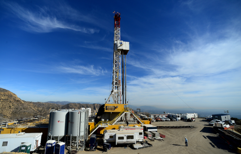
There are two distinct approaches to well integrity assurance adopted in the oil and gas industry. The first is a reactive approach based on monitoring and remedial action. For example, a California gas leak back in October 2015 which took several months to control (see photo). The second approach is a proactive approach like installing a cathodic protection (CP) system to prevent corrosion from occurring as much as possible.
A relief well is being connected to the leaking well in the hopes that all the gas can be diverted there while engineers try to seal the leak. (Dean Musgrove/Los Angeles Daily News via AP, Pool)
External Corrosion Across Aquifers: A Sleeping Threat in the Middle East
Many of the wells producing today in the Middle East were completed several decades ago, where corrosion control and monitoring were not a primary concern. At the initial development stage, there was not enough knowledge and expertise available to anticipate any future fieldwide well integrity problems.
Moreover, the nature of the corrosion mechanism in the Middle East was such that it essentially remained "silent," a "sleeping" threat to a large number of wells. At that time, the observed electrochemical corrosion was not detectable with routine production understanding, surveillance, and geochemical analysis.
As a result, the management of well integrity issues became complicated when numerous corrosion failures suddenly started to occur across shallow-water aquifer levels, especially at levels where wells were cased with multiple concentric casings.
The electrochemical activity, and external corrosion process on multiple barriers, initially concentrated at the outermost casing, which resulted in extensive wall thinning, and in extreme cases, destroyed the outer casing. At its very advanced stage, this general corrosion had broken through to the innermost casing(s), and consequently, holes were developed.
When a casing leak develops, the aquifer water can come in direct communication with production pay through tubing or packer leak, increasing the risk for subsurface blowout and loss of hydrocarbon reserves to shallow-water aquifers. This also imposes another HSE risk by contamination of potable water.
Major Factors Influencing Well Integrity in the Middle East
Field investigations showed there are three primary factors contributing to well integrity issues in the Middle East region:
Lost circulation zones
Piezometric pressure of the shallow aquifers
Hydrodynamic activity of water-bearing zones
Lost Circulation Zones (LCZ): Zones with lost circulation encountered during drilling have a drastic effect on well integrity. Partial or total losses are usually seen in every field starting from surface down to 7500 to 8000 ft. Ineffective primary cement is not unusual, which can result in the outermost barrier being exposed to electrochemical activity.
When openhole logs were acquired across shallow aquifers, they indicated usually porosity in the range up to 40% or even 50%, and permeability in the order of a few Darcys. The resulting productivity or injectivity indices are very high and aquifers are therefore infinite acting.
With a drawdown of just 5 psi, the aquifer can produce more than 5,000 B/D of water to the surface. If no cathodic protection system for the outermost casing is installed, these LCZ will act as “anode.” The LCZ has a very sharp resistivity contrast within the same formation, therefore it acts as an anode. In another case, when there is a cathodic protection system installed, these LCZ will act as a sink for the protection current, and as a result, no solid protection can be achieved below these LCZ.
Piezometric Pressure of Shallow Aquifers: The pressure sampling data acquired from representative wells across the main fields in the Middle East region showed that some potable water reservoirs had piezometric levels above the surface, effectively creating aquifers with high pore pressure. This means that if the well integrity of these wells is compromised due to cement impairment and/or casing corrosion at the aquifer level, water can flow directly to the surface. This can result in a surface flowout, subsurface blowouts, or cross flows in such cases.
Hydrodynamic Activity: The continuous replenishment of oxygen in shallow aquifers results from the typical recharging which occurs from rainwater that runs off from higher ground/hills. This oxygen-charged waterfront is found to be moving, as tracer surveys indicated a speed of 12 m/year in a field in the Gulf region. This hydrodynamic flow can lead to corrosion.
Mitigating Principles To Arrest External Corrosion
Oil and gas operators proactively use an electrochemical technique called a cathodic protection (CP) system to control external corrosion of underground well structures as well as marine structures. CP is also used to control internal corrosion of storage, production, and process vessels that contain water. In many cases, coatings work together with CP systems to help provide more reliable protection and to lower the CP current requirement.
The effects of corrosion can be reduced (and in some cases eliminated) by using resistant metals, inert protective coatings (coated tubing, protective cement sheath), or by introducing chemical inhibitors into the fluid.
Historically, downhole corrosion measurements and data were unfortunately not utilized to design the field CP system, which usually resulted in a low success rate of many CP systems. If combined with corrosion logging and an understanding of the mechanism at play, a successful CP system can be designed.
Getting Feedback on Barriers Properties
Proper wireline corrosion logging at multiple stages over the well life is a critical input in obtaining accurate barrier properties, which may dynamically vary over time. Detailed and consistent log evaluation is applied to obtain understanding on the location, magnitude, cause of the problem, and its impact on well repairs.
Because corrosion can be the result of a wide range of causes, a combination of several monitoring techniques is best deployed to get a comprehensive, synergetic interpretation and accurate understanding of the problem. Additionally, wireline evaluation is essential to optimize the CP system design and to establish the desired design parameters.
Several wireline measurement techniques are available in the market which use electromagnetic, ultrasonic, mechanical, or electrical principles. These technologies can provide a wealth of well integrity data as follows:
Time Domain Electromagnetic Devices: The time domain signal from a pulsed eddy- current measurement has a decay character which is radially sensitive. It has the ability to detect, locate, and measure holes, splits, internal and exterior corrosions, and metal losses in four casings.
Ultrasonic Devices USL: USL uses pulse sound waves that reflect off and resonate within the casing wall, giving internal radius, casing thickness, and cement properties of the innermost barrier.
Mechanical Imaging Devices: The mechanical fingers are used to measure the internal-diameter variations and evaluate the geometry of tubing or casing.
Corrosion Rate Devices: Corrosion rate tools detect current flow along the casing and radial current flow into a formation by measuring potential differences.
Case History: Well Casing Failures in Arab-C Formation
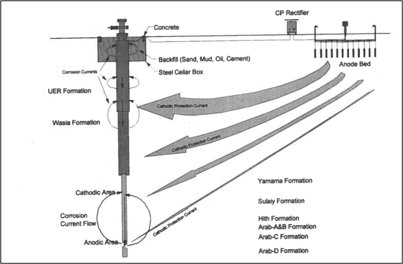
This field case discusses casing failures due to external corrosion in a field despite the impressive current protection system. The Arab- A to C formation were non-problematic in the past but relatively new wells saw the onset of numerous casings leaks. As shown in the figure below, Arab D is the producing reservoir and is located immediately below the Arab- A to C formations and many wells were expected to have through wellbore or behind pipe communication.
External Corrosion Identified Between 6,500 ft to 6,200 ft in Wells Less Than 10-Years Old
A multidisciplinary well integrity team was formed to explore the Arab-C to -D communication problem and review options for maintaining casing integrity in existing and future wells. The team worked to identify and assess the main contributing factors of Arab casing leaks and to recommend preventive measures to avoid a similar reoccurrence in this field and others.
Based on the downhole measurements, it was concluded that severe external corrosion is the result of self-sustained, long-line electrochemical interaction between the Arab-C and other formation fluid, the Sulaiy/Yamama formation, which contacts the casing and establishes a "long-line" corrosion cell. The corrosion results from a combination of an excessively long-time exposure between completion and commissioning of the CP protection system and insufficient cathodic protection itself across the Arab-C reservoir.
Moreover, it was concluded that exceptionally high levels of CP are necessary with a rapid polarization of CP current of 45 amps being required immediately after completing the well.
This case history showed the investigative work carried out to identify corrosion mechanisms primarily by using integrated logs application.
The wireline well integrity logs used in this work were:
Potential profile logs to determine the axial current profile on production under various conditions.
Ultrasonics logs for corrosion and cement evaluation behind the production casing.
Electromagnetic logs for evaluation of single and multiple barriers.
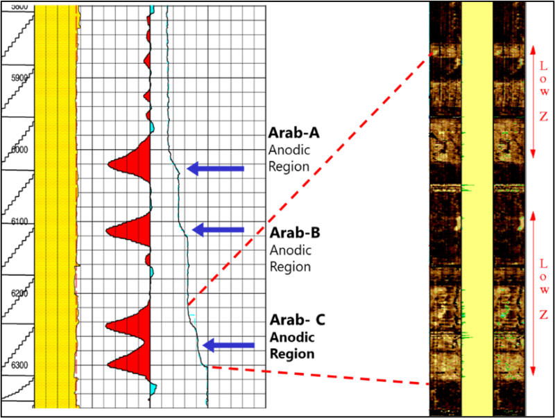
The CP system for the oil well was installed before the well was drilled, ready to be commissioned immediately after well completion. Integrated logs were applied in this well without tubing before applying the CP system, and the plan was run again after 6 months. The figure below shows the diagnostic log application with rectifier output set off. The cement map shown on the right side showed contaminated cement sheath across Arab- C formation due to brine interaction with the cement sheath during setting up of cement. The zones above and below were anhydrite formation, which is the reason behind excellent cement quality. The potential profile survey showed massive anodic currents were discharging from the casing into the formation. All three distinctive anodic zones were located at Arab-A to -C.
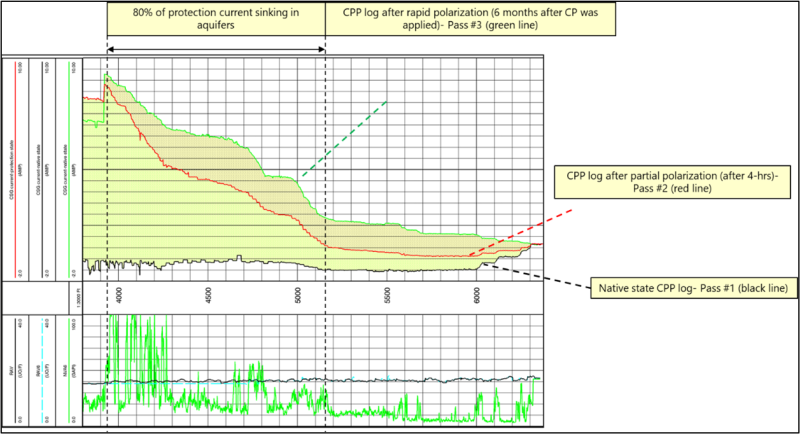
The following figure displays the composite axial casing currents log measured under the following three conditions:
After landing the casing wellbore, no CP was applied (red line)
After 4 hours of partial polarization, CP was applied (blue line)
After 6 months of high, CP was applied (green line)
The main objective of integrated logs at various conditions is to determine if the corrosion mechanism occurring in the Arab-A to -C formation could be mitigated by energizing the high CP system after well completion. Initially, it appeared that high CP would be effective.
Conclusion and Recommendations on the Overall Field Well Integrity Management
Based on experience gained in different projects, it is recommended to study historical and current well integrity data to mitigate well integrity issues. As a result of the study, it is concluded that adopting a strategy of time-lapse corrosion-inspection logging, aiming to investigate the corrosion progress over time in key representative wells, will elongate the production well life expectancy and hence, will aid in prolonging field productivity.
Integrating openhole, geochemical analysis, drilling, and other related datasets, in addition to a deep dive into the well integrity database, will provide insight into the root cause(s) affecting the life of the wells.
The following points summarize the value added by time-lapse logging on key wells across a field.
Identify the corrosion relations between the wells.
Map high-risk areas in the field.
Identify sick wells that require remedy and determine accurate workover planning and CP optimizing, which might mean reducing CP cost by reducing the induced current.
Identify root cause(s) of the well integrity problems across the field and adopt cost-effective solutions.
Allow the production team to plan in a timely manner for any preventive maintenance that might be required to prevent the deterioration of well integrity and possible loss of very important assets, such as a production well, or HSE incidents.
References
NACE-08016: Well Casing Failure Investigation in the Arab-C Formation by Darrell R. Catte
NACE Paper: External Well Casing Corrosion across the Arab-C Reservoir by Ahmad Al Sahhaf and Darrell Catte
SPE 93184 Integrated Analysis of Downhole Corrosion Logs To Investigate Casing Leaks by Y.Y. Al-Ghasham, D.R. Catte, and A.A. Al-Haji, Saudi Aramco : https://doi.org/10.2118/93184-MS
SPE 172736 Solving a Mysterious Casings Failure Problem in ESP-Fitted Production Field by Simina Al Mahrooqi, Muhammad Khalid Azim : https://doi.org/10.2118/172736-MS
Muhammad Khalid Azim
Well Integrity Domain Champion at TAQA
Muhammad.azim@tq.com
Raid Bukhamseen
Senior Manager SAOO Account at TAQA