Mastering Produced-Water Management in Deepwater GOM: 25 Years of Insights
This first of a two-part series provides guidelines for designing and operating advanced produced-water systems on offshore platforms, covering fluid characterization, chemical treatment, equipment, process configuration, operations, and effluent quality.
For many design decisions, the industry is lacking systematic and methodical approaches to treat and manage produced water.
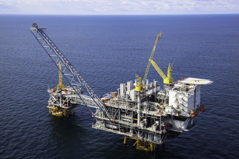
HeliRy/Getty Images
This first installment of a two-part series provides guidelines for the systematic design and operation of produced-water systems specifically for deepwater Gulf of Mexico (GOM) platforms. Six elements are highlighted: fluid characterization, chemical treatment, equipment, process configuration, operations, and effluent quality. The characteristics of the incoming produced water, together with the target effluent quality, define the water-treating challenge.
Due to the high cost of space and weight in the deepwater environment, water treatment must have high intensity and must be highly integrated. High intensity refers to equipment that can handle high volumetric flow rates, over short residence times, and which occupies a small footprint. The concept of highly integrated systems refers to system process design that integrates water-treatment equipment, process configuration, and chemical treatment into a high-performing single system that removes a very high fraction of the contaminants.
Every opportunity is utilized to ensure that the produced water is treated to a high standard. Peak shaving, interface bleed, and break tanks that act as clarifiers are just a few of the opportunities that can be utilized to improve produced-water quality.
Part 1 includes produced water characterization and chemical treatment. Part 2 will cover equipment, process configuration, operations, and effluent quality. It will also include a conclusions section relevant to both Parts 1 and 2.
Introduction
In deepwater Gulf of Mexico (GOM) operations, the separation systems are designed to minimize weight and space while removing a very high fraction of contaminant. A typical oil/water separation system design consists of one or two stages of two-phase gas/liquid separation, followed by a three-phase separator such as a freewater knockout vessel. Produced water from the three-phase separator is then treated for overboard discharge as per the regulatory requirements. In this production scenario, the oil and water droplets have undergone significant shearing because of large pressure drops across chokes and valves. Further, this production scenario limits the ability to make any meaningful impact on reducing the droplet shearing and placing of the water-treatment equipment during the design phase.
The produced-water treatment systems discussed in this article are intended for high intensity deepwater treatment. Currently, there are many rules of thumb and ad hoc methods that guide the design and management of offshore produced-water systems.
However, for many design decisions the industry is lacking systematic and methodical approaches. Very often a produced-water system is designed based on local experience, and on parameters that have led to a successful previous design (Walsh 2019). The problem with this approach is that nearby systems may have fluid properties that warrant a significantly different design approach.
Six Critical Themes Shaping Deepwater Design Innovation
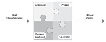
Conceptually, the organization of a design project or an optimization of operations can be thought of as shown in Fig. 1. Six elements or themes are involved. Fluid characterization, which defines the produced-water challenge, is the first theme.
Between the incoming produced water and the discharge effluent are the four elements that provide design specifics for the water-treating system (Fig. 1). These are the elements that contribute to the transformation of a particular feedwater to a very clean desired effluent quality. The elements fit together like a jigsaw puzzle, fitting together closely to form the complete and coherent design.
This article includes produced-water characterization and chemical treatment. Part 2 will include equipment design and operation, process configuration, operations, and effluent produced-water quality.
Fig. 1—The major themes by which technical aspects of produced-water treatment system design can be organized.
Source: Walsh 2019.
Each theme is defined and discussed in a short description and will be followed by a more detailed explanation of the entire system.
It is important to recognize that produced-water samples and characterization data are generally not available during the design phase. Hence, dispersed oil, suspended solids concentration, and particle-size distribution data are also not available.
For characterization, produced-water samples are needed. Sampling is usually carried out where the produced water is split into an oily water stream and wet oil. The wet oil is generally dehydrated, and the produced water is then analyzed. This lack of information must be appropriately addressed during the design phase. Further discussion is presented later in this article.
The chemical treatment indicated in Fig. 1 generally includes coagulants, flocculants, scale inhibitors, oxygen scavengers, corrosion inhibitors, and biocides. We will also include a brief mention of the chemicals typically used in the oil field for other purposes such as oil dehydration (demulsifiers), hydrogen sulfide scavenging, and flow assurance chemicals that are known to have an impact on the performance of produced-water treatment equipment and resulting treated-water quality. An oil-dehydration system plays a very important role in the performance of the water-treatment system. If this system is bottlenecked or constrained, it is likely that water quality will suffer because of adjustments made by operators to achieve dry oil. Further details on chemical treatment will be presented later in this article.
From the standpoint of equipment and process configuration, primary equipment (such as skim tank) provides separation based on density differences between the produced water and contaminants in water. Secondary equipment will include equipment such as hydrocyclones and flotation cells. Tertiary equipment is any equipment that relies on media such as deep bed filtration, membranes, and cartridge filters, and is generally not used by the operators in GOM deepwater. Tertiary equipment (fine filtration, micro-, and ultra-filtration) will not be discussed in this article.
Process configuration (also known as the process line-up, routing, and system integration) and refers to the process flow diagram, i.e., the sequence of tanks and vessels, the connections and routing of process flows, and the all-important routing of reject or recycle streams). This will be presented in Part 2 of the series.
In the design phase of a project, the development of process configuration is known as process integration. Generally, no piece of equipment should be selected until the impact of the equipment on the overall process has been determined. Operators normally further modify these practices based on their field experiences. A given system can perform effectively or not depending on the skill of the operators. The objective of the system is to improve the produced-water effluent quality. Under this theme, we will describe the regulatory guidelines that operators will need to meet for overboard disposal of treated produced water in the GOM.
The following discussion provides detailed information and strategy for designing water-treatment systems for deepwater application.
Characterization of Feed Produced Water
The characteristics of the incoming produced water, together with the target effluent quality define the water treating challenge (SPE 36587, SPE 56847). Each produced-water stream is unique, with characteristics defined by a wide range of variables such as the water source, processing operations, and directly or indirectly added chemicals.
For those sites where waterflooding is conducted, the properties and volumes of the produced water may vary dramatically due to the injection of additional water into the formation to increase hydrocarbon production. Blending of various well streams during the field life is also an important factor in produced-water chemistry. In short, produced water chemistry is never uniform during the field life. Treatment-system design should take this into account.
The produced-water chemistry depends to some degree on process conditions (such as temperature, pressure) and dynamic conditions (shearing, coalescence, settling time), and the use of production chemicals. In the formation, water is in equilibrium with hydrocarbon, and the formation rock material. As the water is produced, the pressure and temperature decrease causing a shift in the equilibria. This may cause various components to precipitate as solid particles. Other components may migrate to oil/water interface. In other words, produced-water chemistry is both a complex and a highly dynamic variable. The system design needs to take this into consideration.
Produced water contains suspended solids, dispersed oil, dissolved minerals and salts, and organic compounds along with dissolved gases, suspended minerals, polymers, and production chemicals. The chemical composition of these contaminants is important in selecting, designing, and operating water treatment equipment.
Important components contaminants of produced water may include
Dispersed oil.
Dissolved oil (oils, BETX, phenols, PAH).
Dissolved organic acids and other organics.
Dissolved or precipitated minerals (NaCl, CaCO3, FeCO3, FeSx, BaSO4, SrSO4).
Dissolved metals (Fe, Zn, Cr, Mn).
Process and production chemicals (corrosion inhibitor, water clarifier, methanol, glycols)
Produced formation solids (clay, sand, carbonate).
Dissolved and precipitated corrosion products (dissolved metals, solid metal hydroxides, and oxides).
Dissolved gases (O2, H2S, CO2).
Combinations of the above (e.g., schmoo, which forms when solids in produced water become coated with oil and chemicals, making them neutrally buoyant. These particles then agglomerate and attract other substances like paraffins, asphaltenes, and bacteria).
Various bacteria and byproducts (e.g., sulfate-reducing bacteria, general heterotrophic bacteria).
The above list is given from the perspective of chemical entities, rather than types of analyses. Many of these entities are determined in typical or standard analyses. The chemical composition of produced water contributes to the
Sensitivity of oil droplets to shear.
Tendency of oil droplets to coalesce.
Chemical treatment to coagulate and flocculate the contaminants.
Precipitation and scaling tendency of dissolved minerals and organic compounds.
Corrosivity of produced water.
Toxicity of produced water.
Selection and design of treatment equipment (equipment type, residence time requirements).
Gas composition and oil characterization (H2S; CO2; C1–C7; BTEX–benzene, toluene, ethyl benzene, xylene; TAN–total acid number).
Water analyses (anions, cations, pH, hardness, dissolved gases, and organics).
Suspended solids concentration, particle-size distribution, composition, and mineralogy.
It is important to recognize that for new projects, produced-water composition and solids data is generally not available because of the lack of good representative produced-water and solids samples during the exploration and developmental phase of the project. Dispersed oil and suspended solids concentration and particle-size distribution data are also not available. By comparison, gas composition and oil are reasonably well characterized. In such a case, analog systemsmust be identified through knowledge of surrounding reservoirs.
Produced-water characteristics from analog fields/reservoirs are then adjusted based on the information from other disciplines in the existing field for developing an understanding of produced-water characterization for design purposes. These include:
Reservoir engineering (crude oil properties, API gravity, TAN, water cut, and geological setting)
Process engineering (gas composition such as H2S, CO2, flow rates)
Flow assurance (asphaltenes, wax, scaling tendency, need for production chemicals for hydrates, scales, asphaltenes)
This type of information can provide insights into the scaling tendency of dissolved minerals, presence of asphaltenes, type of chemicals that may be used for crude oil dehydration, corrosion control, and flow assurance. These all play a very important role in the system design.
Produced-Water Sampling
The importance of using good sampling and analysis practices cannot be overstated. Effective monitoring and troubleshooting of produced-water treatment equipment requires good-quality sampling points both upstream and downstream of all stages of separation equipment.
In selecting the location of the sampling points, the following guidelines are recommended (Walsh 2019), i.e., the sample point should
Be in a vertical section of piping where the fluid flow is upwards.
Be at least five pipe diameters downstream and three pipe diameters upstream of any flow disturbance such as a bend, pump, manifold (ASTM D4177-22Ɛ1).
Be located both upstream and downstream of the deoiling equipment.
Be located both upstream and downstream of control valves and pumps so that the change in drop and particle diameter distribution caused by such equipment can be measured. The sample location should be at least 20 pipe diameters downstream of such equipment. The sample location upstream of this equipment can be as close as a few pipe diameters.
Be in a region of steady, uniform turbulent flow.
Provide an effective, environmentally sound, and safe means for the collection and disposal of the fluid flow required to flush the sample point and sample line.
For sampling points that are used for regulatory compliance monitoring purposes, the following guidance may be considered.
The sampling point should be immediately after the last item of treatment equipment in, or downstream of, a turbulent region, and in any case before any subsequent dilution. The sample point should also be downstream of any installed produced-water volume meter.
The location of the produced-water sample point must be in accordance with the regulatory guidelines and must not be changed without written permission.
Sample points
Should always have a sample probe installed in a manner to ensure a representative sample is taken. The sampling probe should preferably extend to the center of the pipe or at least a distance of 0.25 of the internal diameters of the line away from the pipe walls. In some cases, the length of the probe may be restricted to withstand the mechanical forces exerted by the flow in the pipe.
The internal diameter of the sample probe must be sized to allow for an isokinetic fluid velocity through the probe while ensuring that the volumetric flow rate is within the capacity of the sampling equipment.
Sampling point should be readily accessible and retrievable, if needed.
Spare sampling locations should be strategically provided for future use.
Sampling probes
Sampling probes (also called quills) should be provided for all sampling locations to collect representative samples.
Sampling probes come in a variety of designs such as pitot, circular port, and 45° opening type. An inexpensive and a relatively simple probe design has the end of the sampling probe beveled at 45° (45° opening probe). Such probes are readily available.
Sampling technique, sample handling, preservation, storage, and analysis should be in accordance with well-established procedures.
Chemical Treatment
In this section, we will briefly discuss the chemical treatment program with particular emphasis on what is important during the design phase. The focus should, however, be to ensure that the process can be operated with minimum use of chemicals, whenever possible. Produced-water volumes and chemistry change over the field life. The system design should provide the flexibility to handle varying chemical needs during field life. For example, it may be important to provide spare injection locations, and space for chemical storage and injection equipment for future use, if necessary.
We will briefly describe the overall chemical treatment with particular emphasis on produced-water treatment chemicals, chemical selection, chemical compatibility, and design of chemical injection system.
It is important to optimize the dosage of chemicals injected because they can contribute to an increase in the toxicity, foam, and soluble-oil levels in produced water that can be detrimental in meeting the regulatory overboard disposal water-quality specifications in offshore operations.
Chemical treatment in an oilfield production and processing facility encompasses three areas.
Product/effluent quality—oil, water, and gas quality. The chemicals used to clean produced water include coagulants, flocculants, biocides, corrosion inhibitors, and scale inhibitors. Demulsifiers used in the oil-dehydration process, to meet oil quality, can result in stable emulsions in the water phase.
Flow assurance—chemicals that are injected to prevent wax deposition, scale formation, hydrate control, foam prevention. Flow assurance chemicals have a wide range of properties and mechanisms to manage flow assurance issues in the facility. Some of these chemicals include hydrate inhibitors such as low-dose hydrate inhibitors (LDHI) which can have a major impact on the performance of water-treatment equipment.
Asset integrity—such as corrosion control, hydrogen sulfide scavengers, and biocides. Oilfield corrosion inhibitors generally are surface active and can have an enormous effect on water treatment. Surface active chemicals tend to stabilize both the oil-in-water and water-in-oil emulsions and greatly impact droplet coalescence.
To develop an optimal and holistic chemical treatment program for the facility, all the applications listed above should be considered. Compatibility of various chemicals will need to be tested since one chemical can react with another to make the chemicals ineffective or cause a precipitate or scale to form.
An interdisciplinary team consisting of process engineers, production chemists, and chemical vendors will have to work together to prioritize competing objectives regarding gas quality, oil quality, flow assurance, asset integrity, and water quality. Water quality is especially significant because it must meet regulatory requirements for overboard disposal in offshore operations and injection water quality specifications in onshore operations.
Chemical Treatment: Selection, Compatibility, and Optimization
In most cases, representative produced-water samples are not available during the design phase. Therefore, all the testing for chemical selection will be done in the laboratory using simulated fluids. Composition of fluid samples from analog fields, along with the crude and gas composition from the field being designed, could form the basis for selecting the simulated fluid composition. Laboratory testing should preferably be done simulating process design temperature and pressure as far as practical.
Selecting optimal chemicals for a given process in an existing facility is a multistage process consisting of
1. Characterization of produced water and selection of compatible candidates.
2. Sampling of produced fluids for lab and on-site bottle testing.
3. Bottle/bench testing of candidate chemistries (includes flow-loop tests in the lab, if feasible).
4. Field testing of best chemicals selected based on standard lab and/or on-site bottle testing.
5. Repeating steps 3 and 4 to select the optimal chemical and the dosage.
During the design phase, the chemicals will be selected using simulated fluids and testing in the lab. Lab testing includes bottle/jar testing, bench testing (such as with a bench model flotation unit), and flow-loop testing. They will need to be optimized when the facilities are onstream. Lab testing is also used to determine if there are any compatibility issues between various chemicals selected. Chemical vendors generally have an excellent knowledge of their product’s chemistries and compatibility and will have to be relied upon during the chemical selection process. These tests should be repeated with representative fluids once the facility has been started, both in the lab and in the field, to optimize the chemicals selected and their dosage.
Chemical Injection
For treatment chemicals to be effective, they must be well mixed into the produced water, and they must be given a certain amount of reaction time without high shear prior to mechanical separation.
Chemical-injection system design could be quite complex to accommodate injection into multiple locations at different rates and pressures in the facility. Several chemicals are normally injected in a typical offshore facility. These include downhole, subsea, and topsides applications.
Flow assurance chemicals, hydrate inhibitors (LDHI and thermodynamic hydrate inhibitors such as methanol, and monoethylene glycols), and wax, scale, and corrosion inhibitors are injected subsea.
Asphaltene inhibitors are injected downhole.
Scale inhibitors are sometimes injected in the topside’s facility as well as well as downhole for scale prevention in production tubing.
Demulsifiers are injected upstream of the three-phase separators.
Foam inhibitors are injected upstream of the two-phase separators.
Coagulants and flocculants are injected downstream of the primary produced-water treatment system such as hydrocyclones or upstream of the secondary water-treatment equipment such as flotation units.
Biocides are sometimes used for microbial control in slop tanks. Chemicals are also injected in gas treatment and seawater injection system.
Because of extensive chemical usage, it becomes important to ensure chemical compatibility. It is also important to note that spare injection fittings should be provided during the design phase to ensure chemical injection capability when changing fluid chemistry during the field life could require injection of additional and/or new chemicals. A chemical-injection system includes storage tank, metering pumps, instrumentation, suction/discharge piping, and valves. Most chemical injection systems are skid-mounted to allow safe transport and operation while providing structural protection to the system during routine operation. Chemicals are pumped at the desired rates to the installed injection location and injected into the process stream with an injection quill or an atomizer to ensure proper mixing with the fluid stream.
Injection nozzles are generally used to inject liquids into the gas stream to rapidly disperse the injected stream. This is critical when injection is required to coat/wet the pipe wall with the chemical as, for example, in case of corrosion-inhibitor injection in gas pipelines.
The use of online retractable injection quills allows for the quill to be retracted and inserted without having to perform a complete process depressurization. These quills are preferably inserted to the centerline of the process pipe or at least a distance of d/3 away from the pipe wall to properly disperse the chemical into the solution. The chemical injection system design should ensure that the injection locations are readily accessible and have enough space around for ease in retrieving.
Conclusion
Major conclusions are summarized below.
Six elements or themes are the basis for the systematic design of produced-water treatment systems for offshore GOM platforms: fluid characterization, chemical treatment, equipment, process configuration, operations, and effluent quality.
The characteristics of the incoming fluids, together with the effluent quality, define the water-treating challenge.
In most cases during the design phase, the data on produced water chemistry, dispersed oil, and suspended solids concentration, and particle-size distribution are not available.
Analog systems must be identified through knowledge of surrounding reservoirs. Produced-water characteristics from analog fields/reservoirs should be adjusted based on the information from reservoir engineering, process engineering, and flow assurance from the field under design, to develop an understanding of produced-water characterization for design purposes.
Produced-water quality and volumes vary during the field life. The system design should ensure that these variations are adequately handled.
Good-quality sampling points both upstream and downstream of all stages of separation equipment should be provided for effective monitoring and troubleshooting of the equipment during the field life.
Sampling probes should be installed in accordance with best practices to ensure representative samples can be taken in an environmentally acceptable manner. They should be readily accessible and easily retrievable.
Chemical-injection points should be installed to inject chemicals with a focus on product/effluent quality, flow assurance, and asset integrity in accordance with best practices.
Injection points should have injection quills or nozzles to ensure proper mixing with the fluid stream. These should be readily accessible. The injection quills or nozzles should be easily retrievable on-line.
Chemical selection should be based on laboratory testing with simulated produced-water chemistry (used for system design) and should preferably be done simulating process design temperature and pressure.
John Walsh, PhD, SPE, has worked in the water industry for close to 30 years. He worked for Shell for more than 20 years, Westvaco Paper Company prior to Shell, CETCo Energy Services, and most recently Worley Consultants. At Shell, he was the global subject-matter expert for upstream water treatment. In that role, he worked in dozens of countries, providing oversight for their R&D, troubleshooting and technical programs. He was involved in a wide range of water-treatment challenges including shale, water floor, enhanced oil recovery, and conventional onshore and deepwater offshore projects.
He had the great fortune to work with outstanding produced-water specialists who provided a steady stream of encouragement to write a two-volume book titled “Produced Water.” A list of contributors is given in the cover material of the book.
He was the president and managing director of the Produced Water Society. He has served on the SPE Board of Directors and is the designated instructor for two SPE courses on water treatment. He earned a PhD in chemical engineering from the Johns Hopkins University.
Kris M. Bansal, PhD, SPE,has expertise in developing optimum engineering solutions requiring system integration and interface with multiple disciplines from reservoir to the topsides in upstream oil and gas operations. He recently retired as an Engineering Fellow from ConocoPhillips after 30 years of service, where he was a global subject matter expert in upstream water management. He taught waterflood school and presented problem-solving seminars for technology transfer to operations and engineering. Before joining ConocoPhillips, Bansal spent 6 years at Saudi Aramco in operations engineering, 3 years in activated-carbon research at Calgon, and 8 years in academic research. He has taught SPE courses on water management in shale operations. He holds an MS and PhD in physical chemistry and an MS in chemical engineering. He can be reached at Krismbansal@yahoo.com.