我们衷心感谢 Ken Arnold, PE,他花时间审阅我们的论文并提供专家建议和评论。这些非常有帮助。
Kris Bansal博士、SPE 是一名顾问,擅长开发最佳工程解决方案,这些解决方案需要系统集成并与上游作业中从油藏到顶部的多个学科进行交互。他在康菲石油公司担任工程研究员 30 年后退休,从事勘探与生产工作。他曾在 BP 担任顾问一年,为 BP 墨西哥湾作业提供采出水管理问题的技术支持。他还为 BP 的工程师提供采出水管理方面的培训。
Mastering Produced-Water Management in Deepwater GOM: 25 Years of Insights—Part 2
This article is the second of a two-part series on produced-water management in the Gulf of Mexico and covers four themes: equipment, process configuration, operations, and effluent quality.
For many design decisions, the industry is lacking systematic and methodical approaches to treat and manage produced water.
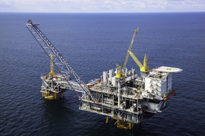
HeliRy/Getty Images
This article is the second of a two-part series and covers four themes: equipment, process configuration, operations, and effluent quality.
Part 1 included an introduction, a brief description of six major themes for produced-water treatment system design, and a more detailed discussion of two themes: the characterization of feed produced water and chemical treatment.
This article includes Part 1’s abstract, and the Conclusion section of this article addresses both Parts 1 and 2.
Abstract
This two-part series provides guidelines for the systematic design and operation of produced- water systems specifically for deepwater Gulf of Mexico (GOM) platforms. Six elements or themes are highlighted: fluid characterization, chemical treatment, equipment, process configuration, operations, and effluent quality. The characteristics of the incoming produced water, together with the target effluent quality, define the water-treating challenge.
Due to the high cost of space and weight in the deepwater environment, water treatment must have high intensity and must be highly integrated with surrounding equipment. High intensity refers to equipment that can manage high volumetric flow rates, over short residence times, and which occupies a small footprint. The concept of highly integrated system design refers to system process design that integrates water-treatment equipment, process configuration, and chemical treatment into a high-performing single system that removes a very high fraction of the contaminants (mostly oil suspended in water).
Every opportunity is utilized to ensure that the produced water is treated to a high standard. Peak shaving, interface bleed, and break tanks that act as clarifiers are just a few of the opportunities that can be utilized to improve produced-water quality.
Equipment
Fundamental information is provided to assist the design team to select equipment for treating produced water to meet regulatory guidelines for overboard water disposal. This includes primary and secondary deoiling equipment—hydrocyclones and flotation cells (Walsh, Arnold, and Stewart).
Primary separation equipment (separators, hydrocyclones) depends on density difference, contaminant (droplet and particle) size, and fluid viscosity. Secondary (flotation) performance depends on contaminant size, interfacial adsorption (which depends on the contaminant chemistry and chemical treatment), bubble size, and total surface area of the bubbles (gas/water ratio). Tertiary separation equipment (such as filters, membranes, etc.) depends on contaminant (floc) size, media surface properties (which depends on the contaminant chemistry and chemical treatment), media surface area, superficial velocity, and details regarding backwash etc.
In the deepwater GOM, the design objectives are met largely through customized design, mainly of hydrocyclones and flotation. These technologies are considered to be “conventional” since they have been available for decades. However, detailed design features of these conventional technologies are not well-known and have only come to light through After Action Review and examination of best practices across the region.
For hydrocyclones, higher pressures (about 150 psig) at the inlet are required for greater flexibility in adjusting operating parameters such as pressure differential ratio and reject ratio for optimal liner efficiency.
Custom design features include small-diameter liners (for greater forward pressure drop and separation efficiency), staging of the throughput (0.25/0.5/ 0.75) has been used with success, and large reject port (for peak shaving). These features can be incorporated into the well-known conventional hydrocyclone.
For flotation, a wide range of approaches have been used to meet design objectives. Customization of flotation equipment includes methods for creating a large number of small-diameter bubbles; number of stages in the equipment design; injection/inline mixing of flotation chemicals; and valving and pipe flow design to minimize shearing. Through performance analysis, the design of single-stage flotation has been found to be inadequate for deepwater application.
The separation efficiency of tertiary equipment will not be discussed in this article because it is generally not required to meet overboard regulatory water-quality specifications and is not normally used in offshore operations.
1. Hydrocyclones—Primary Deoiling Equipment
Hydrocyclones are regarded as “standard technology” in offshore operations for the removal of dispersed oil droplets from produced water and have been successfully used onshore as well. The oil-removal efficiency of a hydrocyclone is the difference between the oil-in-water (OiW) levels of the inlet stream and the water outlet stream divided by the OiW in the inlet stream (Walsh, Arnold, and Stewart).
1.1 Driving Force for Separation
Hydrocyclones utilize liners to generate high centrifugal forces (1,000–2,000 G, where G is the gravitational constant) to classify the influent oil/water stream by density.
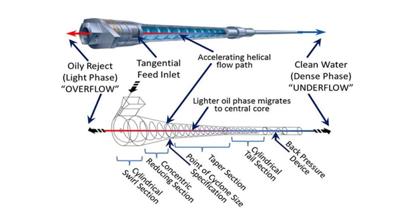
Large centrifugal forces are generated by inducing a swirl motion to the fluid inside the liner. The angular acceleration due to the swirl motion enhances the effect of the density difference between the dispersed oil droplets and water. The oil, being lighter than water, migrates to the axial center of the liner. This core of oil flows in the opposite direction of the water effluent due to pressure difference between the feed and the reject orifice. As shown in Fig. 1.1, the oil is directed to a reject port (overflow), and the water exits through an effluent port (underflow in Fig. 1.1). The reject core is drawn out of the reject orifice at the top of the cyclone liner.
A modified Stokes’ Law equation for separation of oil droplets from water applies.
V0 = Fc * 1.78 * 10-6 (Dr) d2 /µ
Where Fc is the centrifugal force, multiples of gravity, V0 is the vertical velocity of the oil droplet in ft/sec, d is the droplet diameter in microns, ∆ρ is the specific gravity difference between water and oil, and µ is fluid viscosity in centipoise. The migration rate of the oil droplets to the central core (or axis) is controlled by the same variables in Stokes’ Law with one exception. Stokes’ Law is based on gravity as the driving force whereas in a hydrocyclone the centrifugal acceleration of the swirl motion provides the driving force.
Various Liner Sections
A liner has four sections—a cylindrical swirl chamber, a concentric reducing section, a fine tapered section, and a cylindrical tail section (Figure 1.1). The location between concentric reducing section and taper section is the point of cyclone size specification (hydrocyclone diameter). Fluid acceleration (tangential velocity) occurs in the reducing, taper, and parallel sections. The reducing and taper sections have a conical shape, and the parallel section has a cylindrical shape.
Fig. 1.1—Schematic diagram of a single cyclone with labeled sections and showing geometry and fluid path of a typical deoiling cyclone. Such a cyclone is typical of that used in packaged deoiling hydrocyclone units.
Packaging of Liners
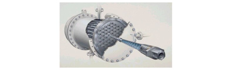
Most offshore hydrocyclone installations have a pressure vessel that houses many liners (Fig. 1.2). The most common packaged unit has a single feed stream and a single product and reject stream.
Fig. 1.2.—Packaging of many cyclonic liners within a single pressure vessel. This cutaway diagram shows the reject header and the feed section below the reject header. A single liner is shown in some detail, including the O-rings which seal the liner into the reject header.
Packaging is an important aspect of hydrocyclone installation. Manufacturers have developed many varieties of packaging which have various desirable features. The design team will need to review various packaging to select the most appropriate for the design project.
It is important to select a reasonable number of liners in each pressure vessel (such as between 50 and 60). Based on operational and maintenance considerations, it may be useful to select the number of liners in each pressure housing to process roughly 25% of the total produced-water rate or a maximum of about 50,000 BWPD.
It may be advantageous to provide a spare pressure vessel to be used when one of the vessels with liners is out of service for maintenance, especially in offshore operations.
1.2 Operating Principles
1.2.1 Separation, Capacity, and Equipment Cost
Separation efficiency depends strongly on the diameter of the liner. The smaller the diameter, the lower the liner throughput capacity, but the higher the swirl velocity and the greater the driving force for oil/water separation. Lower capacity means more liners will be required for a given water flow rate, and subsequently, equipment cost will be higher.
In deepwater operations, droplet size is very small because of excessive shearing and limited room for long pipe runs to allow droplet coalescence. Based on this, smaller-diameter (high-efficiency) liners are preferred. That is one of the basic decisions that will need to be made when selecting the liners.
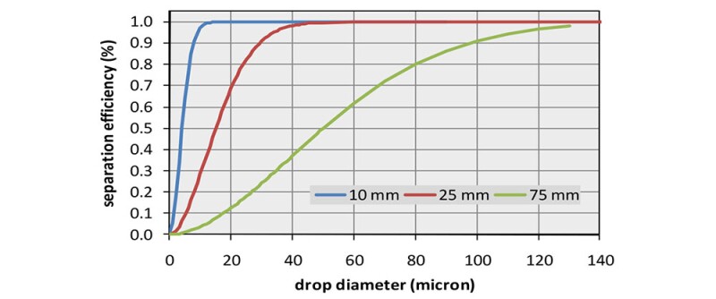
The curves in Fig. 1.3 were generated for different liner sizes based on empirical correlations for a specific set of density difference and water viscosity. Differences in these variables will change the results but not the overall conclusions.
Fig. 1.3—Typical separation efficiency curves for various hydrocyclone designs.
For deepwater offshore operations, smaller-diameter hydrocyclones (such as 10 mm or 25 mm) are preferred to remove small-diameter (<20 microns) dispersed oil droplets.
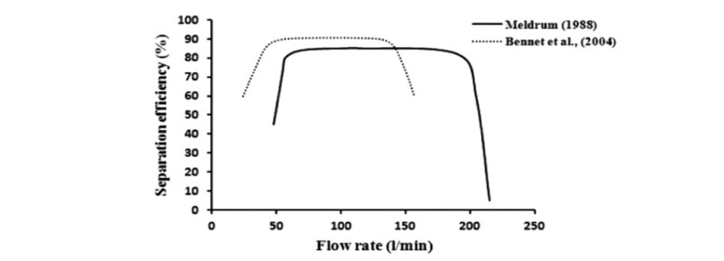
1.2.2 Flow Rate and Hydrocyclone Separation Efficiency (Operating Envelope)
Turndown Ratio. As shown in Fig. 1.4, the separation efficiency of a hydrocyclone typically increases as the flow rate increases and remains constant over a wide range of flow rates. At a certain high flow rate, the separation efficiency starts to drop rapidly. The hydrocyclone designs from each manufacturer have their unique curve. The curves in Fig. 1.4 show a turndown ratio which is approximately 4 to 1. For operational purposes, it is best to use the hydrocyclone at 80% of its maximum rated flow rate to handle fluid rate fluctuations from slugging generally observed in operations.
Fig. 1.4—The separation efficiency as a function of the flow rate over a wide range of flow rates.
Pressures
Three pressures are important to the optimization of fluid flow and separation efficiency in the hydrocyclone: (a) forward or inlet pressure, (b) treated effluent or underflow pressure, and (c) reject or overflow pressure.
Underflow pressure is a function of the inlet pressure and volumetric flow rate of liquid through the hydrocyclone, which creates a pressure drop.
In a typical installation, the hydrocyclone is connected to a separation vessel with the level-control valve of that vessel downstream of the hydrocyclone. Thus, the inlet pressure is the pressure in the vessel and the underflow pressure becomes the upstream pressure to be used in sizing the vessel’s level-control valve.
The difference between the inlet pressure and the underflow pressure is called the forward pressure drop. The importance of the forward pressure drop cannot be overstated yet it is often specified incorrectly. This pressure drop should be maximized since it provides the driving force for separation. The inlet pressure is provided by an upstream separator or a suitably (low-shear) selected pump and is the highest of the three pressures. For design purposes, it is preferred that this feed pressure is greater than about 125 psig or preferably around 150 psig. High inlet pressure pushes the fluid through the liner, generating high centrifugal forces.
Low pressure in the fluid core permits the reverse flow of the oily water to the reject port (reject orifice). The reject port is a very small orifice that is about 1–3 mm in diameter. This is designed to ensure that the hydrocyclone reject rate is small and only the fluid from the central oily core flows in the direction of the overflow.
Overflow pressure is controlled by external valves and the valve-control system.
Reject Ratio. The ratio of the reject or overflow rate to the inlet flowrate is called the reject ratio. It is modulated by adjusting valves on the overflow and underflow discharge piping.
Reject Ratio = (Overflow rate/Inlet flow rate) * 100
Hydrocyclone systems have an optimum reject ratio. Systems operating at less than the optimum reject ratio will result in lower oil removal efficiency. A margin of safety may be determined by quantifying the decline in removal efficiency as a function of the reject ratio. In most cases, this reject ratio is about 2.5.
Dispersed particles in the oily reject stream can result in plugging of small reject orifices (about 2 mm) and impact oil-removal efficiency. This can be corrected by periodic backflushing of the reject orifices.
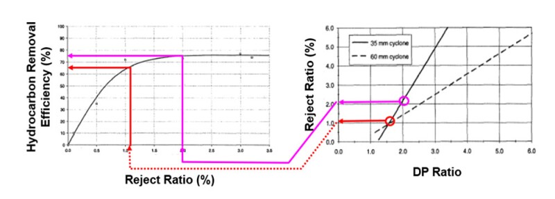
Pinlet is the inlet pressure, Preject is the pressure at the reject port or Poverflow, Pwater outlet is the pressure at the water outlet stream or P underflow. For oil and water separation, the optimal PDR is between 1.7 and 2.0, and the exact PDR will need to be determined during operation.
PDR must be greater than 1 to force the oil in the core to go in the reverse direction of flow. For a given hydrocyclone geometry, the PDR controls the amount of fluid that is rejected. Fig. 1.5 provides insight into the relationship between the PDR, reject flow rate, and the separation efficiency. The figure on the right is the relation between the reject ratio and the PDR. Fig. 1.5shows the relationships between two particular hydrocyclone designs.
Figure 1.5—Two diagrams together demonstrate the effect between DP ratio (PDR) and separation efficiency. The two of these variables are tied together through the reject ratio.
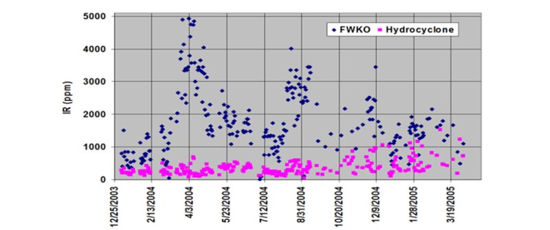
Performance Data. Field data for hydrocyclone performance on the Auger platform in 2004 is presented in Fig. 1.6. The data shows that the primary benefit of the hydrocyclone is to significantly reduce the oil concentration downstream of it (peak shaving). This can significantly improve the performance of the downstream water-treatment equipment such as flotation cells. The gradual deterioration of hydrocyclone performance (squares) that started in October 2004 was due to a reduced backwash frequency and lower flow rates without adjustment of the number of liners.
Fig. 1.6—Field data. Oil concentration as measured by IR at the FWKO discharge (diamonds, hydrocyclone feed) and the hydrocyclone discharge/flotation feed (squares). Note that FWKO discharge (feed to hydrocyclone) attains very high values. The main benefit of the hydrocyclone is to “peak shave.” This improves flotation performance.
1.3. Hydrocyclones—Advantages and Drawbacks
1.3.1 Advantages
Peak shaving
Fluid residence time about 2 sec
Flexible modular design.
Easy to operate and maintain. No moving parts.
Removes oil droplets >15 microns very efficiently in most cases
Broad and predictable operating range
Insensitive to platform motion
Insensitive to slugging
Quick startup and recovery from upsets
Oily water reject rate is about 2%
1.3.2 Disadvantages
Sensitivity of the hydrocyclone system efficiency on droplet size distribution
Requires relatively high pressure (about 150 psig) for optimal hydrocyclone performance
Requires a low-shear pump to boost operating pressure in low-pressure systems
Small-diameter reject port prone to plugging, thus requires regular backflushing to minimize blockage potential
Performance deteriorates in the presence of oil wet solids
2. Flotation Cells—Secondary Deoiling Equipment
In this section, we briefly describe the basic information that the design engineer should consider for selection of flotation equipment for a given application. We do not describe details of various types of flotation equipment but simply present guidelines that will assist design engineers in selecting equipment.
Flotation is a secondary process. If hydrocyclones are present in the system, flotation is always located downstream of the hydrocyclones.
Flotation is typically capable of separating small amounts of oily solids along with dispersed oil particles and thereby increases a system’s efficiency. Gas flotation equipment is generally more efficient in dispersed oil removal when compared with liquid-liquid hydrocyclones because of its ability to remove both dispersed oil droplets and at least some oily solids.
Flotation units utilize finely dispersed gas bubbles to carry dispersed oil droplets and oily solids to the surface. Oil droplets and oily solids adhere to the surface of the bubbles and rise to the surface with a velocity that is estimated from Stokes’ Law. The attachment of dispersed gas bubbles to the oil droplet and oily solids reduces the specific gravity, thereby producing a faster rise and accelerating their separation.
Chemicals are used to coagulate and flocculate the dispersed droplets. Gas bubbles and flocculated droplets form a froth layer on the water surface, and contaminants on the surface are removed by skimming.
2.1 Mechanism of Separation
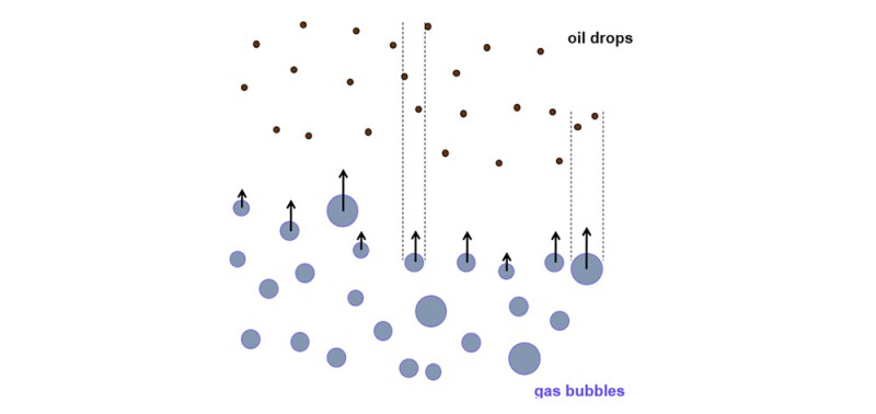
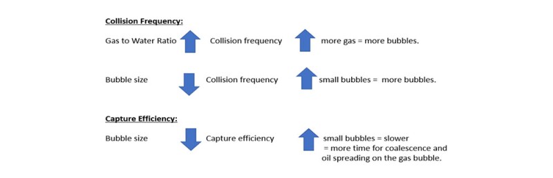
In a flotation cell, gas bubbles are injected or induced. Gas bubbles rise rapidly and collide with the oil drops. The collision frequency depends on the concentration of oil drops, the concentration of gas bubbles, and on the projected areas of the oil drops and the gas bubbles. Very few collisions lead to the capture of oil drops by gas bubbles. This is known as the “capture efficiency.” This is roughly 1/1000. It is important to note that capture efficiency is much smaller when large bubbles are used when compared with the capture efficiency when small bubbles are used. Capture efficiency depends on the surface chemistry of oil and gas. It is strongly affected by chemical additives such as coagulants and flocculants.
Fig. 2.1—Schematic illustration of gas bubbles rising (blue dots) and oil droplets. The collision path of two of the bubbles is shown.
Fig. 2.2—Collision frequency and capture efficiency.
Fig. 2.2 is a schematic showing the impact of gas-to-water ratio and bubble size on collision frequency and capture efficiency. For improved separation of dispersed oil droplets from produced water in a flotation cell, small bubbles and high gas/water/oil ratio are needed.
2.2 Design Considerations
Flotation is a contact separation process. It relies on the contact of gas bubbles with oil drops and solid particles. The important variables are:
Gas/water ratio (volumetric ratio)
Bubble size (diameter)
Staging (single, dual, multistage)
Chemical application (surface chemistry), such as coagulants and flocculants
Contaminant size and surface chemistry
Design variables include large contaminant oil droplets and oily solid particles, uniform bubble distribution throughout the flotation cell, high gas/water ratio, and small (optimal size) gas bubbles. The bubble size should be minimized while ensuring that the bubbles are large enough to migrate to the oil/water interface. The contaminant size can be increased via chemical usage such as coagulation and flocculation. These chemicals are injected downstream of the hydrocyclones but upstream of the flotation cells. The use of multiple stages in a flotation cell is a very effective way of increasing the separation efficiency. For example, in most applications, horizontal hydraulically and mechanically induced flotation cells routinely use four separation stages. The total fluid residence time in a flotation cell is about 5 minutes. In addition to the aforementioned variables, there are a few important practical considerations in the mechanical design.
The oily water must be introduced in a way that does not disrupt the flotation process.
The wet oil and clean effluent water must be discharged in a way that does not allow contamination with the feed and that does not disrupt the process.
The overall weight and space must be as low as possible, while achieving a high separation performance.
The reject stream from the flotation cell must be properly handled (such as in a properly designed slop tank) to ensure minimal impact on the overall produced-water treatment system. This reject stream in a multistage flotation unit is normally between 5 and 10% of the incoming flow rate to the cell.
As with most water-treatment equipment, integration of the flotation unit into a facility or process is critical to successful performance. The most important aspect of integration is handling the reject.
2.3 Flotation Equipment
There are four types of gas flotation cells that are used in the upstream oil and gas industry (Walsh Arnold, and Stewart).
Vertical induced gas flotation—commonly used offshore in deepwater operations
Almost all horizontal units are multistage. We do not provide any details on the equipment but will simply highlight some features that can help design engineers in selecting the most appropriate unit for the application.
2.3.1 Dissolved Gas Flotation (DGF) Unit
In a DGF, gas is dissolved into a recirculating recycle clean-water stream (about 20– 25%) at high pressure (around 20–40 psig). Natural gas is generally used to exclude oxygen. The gas- saturated water then passes through a valve and into the flotation chamber. The dissolved gas breaks out of the solution in small-diameter bubbles (20 to 60 microns) when the flow enters the chamber. These bubbles are much smaller than in a typical induced-gas device which are approximately five to 10 times larger. Dissolved gas generally is between 0.2 to 0.5 scf/bbl of water to be treated.
The amount of gas that can be injected into a DGF is limited due to two factors. The first is a thermodynamic limitation of gas solubility that depends on the temperature of the water and pressure of gas. The second factor is the practical limit in how much treated water can be recycled to inject the gas into the feedwater. Although small bubbles are generated in the DGF, the total number of bubbles is relatively small because of the limitations of volume of the injected gas. So, in most cases, the overall separation efficiency is around 50%. DGFs can be single or multistage units.
DGFs are not commonly used the upstream oil and gas industry because of low separation efficiency.
2.3.2 Horizontal Hydraulically Induced Flotation Unit
In these units, gas dispersion is achieved by circulating a portion (about 25%) of the clean effluent water in each cell section. This water re-enters the flotation cell through a venturi which draws gas from the vapor space over the water in the cell and discharges it with the water into the bottom of the cell. These hydraulic units are mostly four cells.
The capacity of the unit must be designed to handle the feed (untreated influent) plus the recirculated water.
2.3.3 Horizontal Mechanically Induced Flotation Units (Such as Wemco)
These units achieve gas dispersion with a rotor turned by an electric motor. As the rotor turns, it acts as a pump forcing water through a disperser and creating a vacuum which pulls gas from the gas blanket into a standpipe and mixes it with water. As the gas-water mixture moves through the disperser, small gas bubbles form. The gas bubbles thus formed gather the oily floc and bring it to the surface where it is skimmed off. In general, the efficiency of a mechanically induced gas flotation cell is higher than the hydraulically induced cell. However, due to higher maintenance costs associated with multiple motors and rotors, hydraulic units are often preferred over mechanical units.
2.3.4 Staging and Removal Efficiency
As mentioned before, horizontal flotation units are generally multistage. In a four-cell unit, the total fluid retention time is typically 5 minutes. Bulk water flow moves in series from one cell to the other by underflow baffles. Water flow from one cell to the other is basically in a plug flow mode.
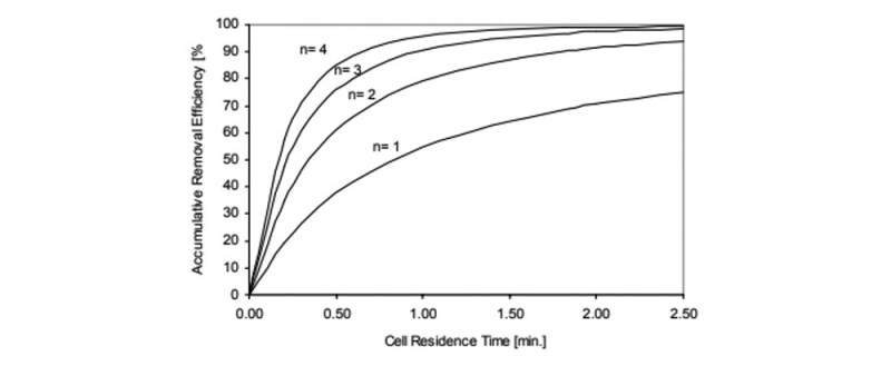
Flotation kinetic analysis has long been used to predict the contaminant removal efficiency in an IGF (induced gas flotation) process. Based on this analysis, efficiency is a direct function of the cell residence time and the number of cells (Movafagian et al). Fig. 2.3 is based on the kinetic analysis. It shows that in a single cell unit, the maximum contaminant removal efficiency is about 70%, even if the fluid residence time is increased to 2.5 minutes. The design engineer should take this into consideration.
Fig. 2.3—Contaminant removal efficiency as a function of cell residence time and number of cells.
2.3.4Vertical Induced Gas Flotation Units (VIGF)
VIGFs (typically single stage) were originally designed to address concerns about the effect of wave motion on deepwater floating structures, to reduce footprint, and as a lower-cost alternative to the large multistage horizontal units discussed above. VIGFs have performed well; however, single-vessel applications can be prone to upsets, offering no redundancy or protection against mechanical failure.
When vertical flotation units are required to meet system design or space limitations, the use of two or more vessels in series should be considered because of low efficiency for single-cell units as shown in Fig. 2.3. Currently, the main advantages offered by vertical IGF are low cost and reduced space requirement and weight.
Gas bubbles in a typical VIGF are generated either by using eductors (hydraulically induced such as in a Unicell), or in some designs, specialized pumps are used to generate gas bubbles. However, in all these VIGFs, single stage is used and the fluid residence time varies between 2 to 5 minutes.
The vertical configuration lends itself to the use of vessel internal elements that promote uniform distribution of gas, good gas bubble/oil drop contact, and coalescence of oil drops. This has led to sophisticated internal elements, which make these units significantly different from the classic horizontal IGF units. A major disadvantage of using coalescing elements is their tendency to become plugged by suspended solids present in produced water.
The efficiency of a four-unit flotation cell is higher than a single unit cell.
Induced gas flotation units have higher efficiency than dissolved gas units.
Experience has shown that mechanically induced flotation units have higher efficiency than hydraulically induced flotation units.
In general, oil droplets greater than about 10 microns are efficiently removed in flotation units.
A proper design and operation of induced gas flotation units should be capable of around 90% dispersed oil removal.
2.5 Flotation Cell Advantages and Disadvantages
Advantages
Well-known process with long operating history
Function does not depend entirely on the density difference between the oil and the water phase
Good turndown (longer residence time, improved separation)
Effective system for removing dispersed oil, especially when used with chemical addition (coagulants and flocculants)
Generally, achieves, if properly operated and maintained and used in conjunction with properly designed primary deoiling equipment, a dispersed oil concentration in overboard water of less than 29 mg/L
Oil droplets >about 10 microns are efficiently removed
Disadvantages
Fluid residence time is relatively long (around 5 minutes). Equipment is relatively heavy and bulky.
Not suited for floating production systems.
Needs a steady constant feed. Vulnerable to upset shock loads of oil with subsequent slow recovery.
Vulnerable to changes in flow and water composition which may result from startup/shutdown of individual wells.
Carryover of oily floc from flotation cells is difficult to eliminate, which can degrade effluent water quality and can cause sheen on the surface of receiving waters.
Generally, very sensitive to chemicals and their dosages.
Manpower-intensive with respect to operation and maintenance.
Shearing of oil droplets may occur across eductor nozzle in hydraulically induced cells or rotor in mechanically induced flotation units.
3. Process Configuration
Process configuration refers to the process flow diagram, i.e., the sequence of tanks and vessels, connections and routing of process flows, and the all-important routing of reject streams. Many different process flow diagrams could be devised for a given project. Variations include use of degassing vessels, design of closed drain system, pumps, valves, instrumentation that provides motive flow, and control of levels and fluid flow are all part of the process configuration. In the design stage of a project, the development of a process configuration is known as process integration. Generally, no piece of equipment should be selected until the impact of that equipment on the overall process has been determined. The design team evaluates various process flow diagrams and finally selects the one that is most appropriate for the project (Walsh).
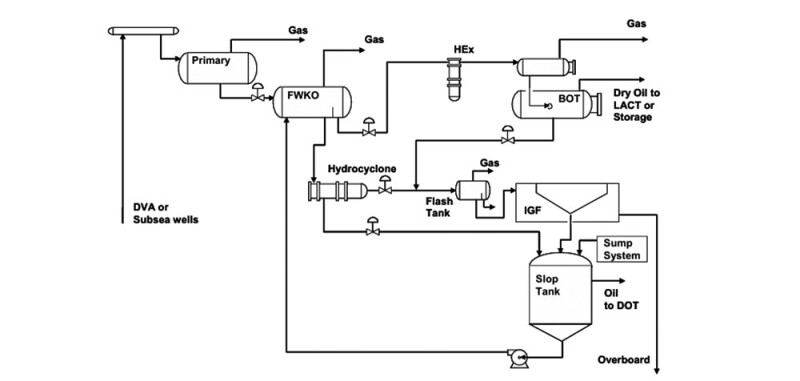
A process flow diagram (PFD) which is a composite of systems on various GOM platforms is shown in Fig. 3.1. Hydrocyclones and flotation cells are used for oil/water separation.
Fig. 3.1—A composite process flow diagram representing the essentials of the process system typically installed in GOM deepwater operations.
It is important for the design team to take into consideration some of the best practices for removing dispersed oil from produced water during selection of the most appropriate design for the facility. These best practices include:
Minimize droplet shear in valves and pumps.
Maximize pipe lengths between shearing mechanisms and downstream separation equipment to promote pipe coalescence of droplets.
Apply heat to the fluids far upstream to facilitate oil/water separation.
Separate water early in the system, if possible, to prevent droplet shearing.
Prevent solids production and provide equipment to separate and remove solids (e.g., conical bottom slop tank).
Consider the use of positive displacement pump rather than a centrifugal pump on the discharge of the slop tank.
Provide an effective rejects-handling system.
Provide an effective chemical-treatment system.
Provide an effective monitoring and control system.
We focus on the rejects-handling system only because of issues that we have observed in properly handling the rejects in many existing facilities. From the standpoint of overall system, the reject is a recycle stream. It represents an endless list of possible process problems in terms of compatibility, contamination, flow-rate fluctuations, and so on. If not managed properly, it can cause the entire system to struggle in many ways and cause poor effluent water quality.
All water-treating equipment generates a reject stream. In many cases, it is desirable to route the reject stream through the primary separation process. In selecting equipment and designing an oil/water separation system, it is important to consider the flow rate and oil-in-water concentration of all reject streams. A material and flow balance of the overall process is required. If the primary separation equipment is not adequately sized to manage both the reject and the primary production stream, then the system will be bottlenecked. Realistic values of reject rate must be used in sizing the vessels which will manage both the reject and the primary production stream. If the vessels are not properly sized, the operators will be forced to reduce either the oil-retention time, the water-retention time, or the reject flow rate. Any one of these steps will result in poor oil and/or water quality. On a deepwater offshore platform, there are typically only three discharge streams—dry-oil pipeline, dry-gas pipeline, and treated produced water for overboard discharge.
In Fig. 3.1, a cone-bottom slop tank is shown for managing the reject stream. Fluids from the slop tank are recycled back into the process stream.
It is important to properly design the slop tank to minimize process upsets. This tank can be used to provide settling time and another opportunity for chemical treating. Provisions should be provided for heating the fluids to a temperature of 120°F or higher for improved separation into oil/water/solids.
The settled solids in the cone bottom tank should be periodically removed and hauled for eventual disposal onshore.
The chemically stabilized emulsion pad containing separated oil and oil wet solids should preferably be pumped directly into the oil pipeline or to a separate tank for further processing offshore or onshore in a specially designed skid. This should not be recycled back into the process stream. Typically, the oily emulsion when pumped into the oil pipeline will contribute to the BS&W of the sales oil, so this must be done within the limits of the oil dehydration specification.
The separated water can be recycled back into the process stream or to a separate tank for further processing in a specially designed skid. Water quality for this fluid stream should be checked before it is recycled back into the process continuously at a slow rate (preferably less than 5% of the total rate through the system) to minimize the potential for process upsets. Clarified water from the top of the slop tank should be recycled to the inlet of the water-treatment system and not to an upstream separator where residual chemicals and solids can contribute to the formation of the interface emulsions which can upset the treatment process.
4. Operations Input
It is extremely important that the design team has very good participation from the operations representatives in all phases, starting with the conceptual design and ending when the design team hands over to operations. Operations representatives have enormous practical experience in operating the facilities and can provide very valuable input on what works and what needs improvement (Walsh). They can provide excellent input, especially in the following areas.
Lessons learned from the design and operations of other facilities. These should be incorporated for improved facility design.
Detailed engineering design, equipment selection, and construction phase.
Development of operating procedures and practices.
Development of commissioning and startup procedures.
Operations participation will greatly facilitate the handover of the facility operation from the design team to operations.
5. Effluent Produced-Water Quality for Overboard Disposal
Governmental regulations govern the water-quality parameters needed for overboard disposal. For example, in the US federal waters (designated legally as the Outer Continental Shelf (OCS)), the Environmental Protection Agency (EPA) created the Clean Water Act (CWA) in 1972, which then created the NPDES (The National Pollutant Discharge Elimination System) permitting program.
Overboard disposal of produced water in the GOM must be authorized by a permit issued under the NPDES program and must meet regulatory guidelines detailed in the permit. We briefly describe these guidelines below.
The oil and grease content of produced-water discharge must be below a daily maximum of 42 mg/L and a monthly average of 29 mg/L. Samples for oil and grease monitoring shall be analyzed at least once per month.
No visible sheen on the surface of the receiving waters. A produced-water sample shall be collected, within 2 hours of when a sheen is observed and analyzed for oil and grease. The regulatory procedure is US EPA-1664.
Toxicity shall be assessed through a 7-day chronic Whole Effluent Toxicity (WET) test in accordance with Short Term Methods for Estimating the Chronic Toxicity of Effluents and Receiving Water to Marine and Estuarine Organisms (EPA/821-R-02 014), or the most current edition. To be in compliance with a WET limit, the No Observable Effect Concentration (NOEC) must be equal to or greater than the critical dilution (percent effluent) concentration specified in Appendix D, Table 1 of the NPDES permit.
The critical dilution concentration calculated from Table 1 of the permit depends on the discharge rate, discharge pipe diameter, and the water depth between the discharge pipe and the bottom. The NOEC is defined as the greatest effluent dilution which does not result in lethality, compared to the control sample. Produced-water sampling methods, sampling frequency, sample preservation, and analytical techniques for sample analysis, toxicity testing, and reporting requirements are detailed in the NPDES permit. The reader should refer to the NPDES permit for details.
6. Conclusions
Major conclusions from Part 1 and Part 2 are summarized below.
1. Six elements or themes are the basis for the systematic design of produced-water-treatment systems for offshore GOM platforms. These themes are fluid characterization, chemical treatment, equipment, process configuration, operations, and effluent quality.
2. The characteristics of the incoming fluids, together with the effluent quality, define the water-treating challenge.
3. In most cases during the design phase, data on produced-water chemistry, dispersed oil and suspended solids concentration, and particle size distribution data are not available.
4. Analog systems must be identified through knowledge of surrounding reservoirs. Produced-water characteristics from analog fields/reservoirs should be adjusted based on the information from reservoir engineering, process engineering, and flow assurance from the field under design for developing an understanding of produced-water characterization for design purposes.
5. Produced-water quality and volumes vary during the field life. The system design should ensure that these variations are adequately managed.
6. Good-quality sampling points both upstream and downstream of all stages of separation equipment should be provided for effective monitoring and troubleshooting of equipment during field life.
7. Sampling probes should be installed in accordance with best practices to ensure representative samples can be taken in an environmentally acceptable manner. They should be readily accessible and easily retrievable.
8. Chemical-injection points should be installed to inject chemicals with a focus on product/effluent quality, flow assurance, and asset integrity in accordance with best practices.
9. Injection points should have injection quills or nozzles to ensure proper mixing with the fluid stream. These should be readily accessible. The injection quills or nozzles should be easily retrievable on-line.
10. Chemical selection should be based on laboratory testing with simulated produced-water chemistry (used for system design) and should preferably be done simulating process-design temperature and pressure.
11. Hydrocyclones and flotation cells, commonly used as primary and secondary deoiling equipment in deepwater offshore operations, are well suited for produced-water treating.
Hydrocyclones
Most offshore hydrocyclone installations have a pressure vessel containing several liners. Based on operational and maintenance considerations, suggested number of liners should be in the range of 50 to 60 in each pressure vessel to process about 25% of the total flow rate of produced water or a maximum of 50,000 BWPD. The number of pressure vessels should be n+1 where n is the number of vessels required to treat the total produced-water rate, and the extra (spare) vessel is for use when a vessel is off-stream for maintenance.
Smaller-diameter liners (such as 15 or 25 mm) should be used to efficiently remove oil droplets greater than 20 microns.
A feed pressure of 125–150 psig or higher at the inlet of the hydrocyclone is recommended to provide operations flexibility.
A pressure differential ratio of about 2 and a reject ratio of about 2.5 are generally considered to be near optimal.
It is best to use hydrocyclones at 80% of their maximum rated flow rate to manage fluid fluctuations resulting from slugging.
Flotation Cells
Multistage (four stages) horizontal hydraulically induced and single-cell vertical induced flotation units are commonly used in deepwater operations. Fluid residence time in a horizontal flotation unit is about 4 to 5 minutes.
Oil droplets greater than about 10 microns are efficiently removed in a flotation unit.
The efficiency of a flotation unit is a direct function of cell residence time and the number of cells.
Maximum contaminant removal in a single-cell vertical flotation unit is about 70%, even at a fluid residence time of 4 minutes. This should be an important consideration during the design phase. A two-cell vertical flotation unit is more suited for efficient operation.
A four-cell horizontal flotation cell has an efficiency of about 90% for contaminant removal.
The design rate of the flotation unit should include the rate of the recycle stream used for inducing gas into fluid. In a multistage hydraulically induced floatation cell, the recycle stream is about 25% of the treated fluid stream.
12. It is critical to properly design a slop tank to handle the rejects stream. Design should include provisions for hauling of the separated solids for onshore disposal and for recycling of the emulsion pad directly to the sales oil line to minimize process upsets and deoiling-equipment performance. 13. Design of a produced-water-treatment system should consider the rate of the recycle streams from the slop tank and the quality of the fluids being recycled.
14. Operations representative should be a member of the design team, and the input on best practices and lessons learned from design and operation of previous facilities should be carefully considered by the design team for improved facility design.
15. Design teams should base their facility design on meeting the effluent treated produced-water quality as required by governmental regulations.
Acknowledgment
Our sincere thanks to Ken Arnold, P.E., for taking time to review our paper and for providing expert advice and comments. These were very helpful.
Kris Bansal, PhD, SPE, is a consultant with expertise in developing optimum engineering solutions requiring system integration and interface with multiple disciplines from reservoir to the topsides in upstream operations. He retired as an Engineering Fellow from ConocoPhillips after 30 years of service in E&P. He spent a year at BP as a consultant providing technical support on produced water management issues in support of BP’s Gulf of Mexico operations. He also provided training in produced water management to BP’s engineers.
At ConocoPhillips, he was the global subject matter expert in upstream water management, providing technical and problem-solving expertise in ConocoPhillips worldwide operations to develop innovative, cost-effective, and environmentally sound solutions to process problems. He taught waterflood school and presented problem solving seminars for technology transfer to operations and engineering in ConocoPhillips.
Before joining ConocoPhillips, he spent 6 years in Saudi Aramco (Ghawar Field) in operations engineering and 3 years at Calgon Corporation in activated carbon R&D. Prior to joining industry, he spent 6 years in academic research at Carnegie-Mellon University and Han Meitner Institute of Nuclear Research in Germany.
Having earned an MS and PhD in physical chemistry and MS in chemical engineering, together with extensive experience in operations, he provides a unique combination of fundamental knowledge with firsthand practical experience to organizations. He can be reached at krismbansal@yahoo.com.
John Walsh, PhD, SPE, has worked in the water industry for close to 30 years. He worked for Shell for more than 20 years, Westvaco Paper Company prior to Shell, CETCo Energy Services, and most recently Worley Consultants. At Shell, he was the global subject-matter expert for upstream water treatment. In that role, he worked in dozens of countries, providing oversight for their R&D, troubleshooting and technical programs. He was involved in a wide range of water-treatment challenges including shale, water floor, enhanced oil recovery, and conventional onshore and deepwater offshore projects.
He had the great fortune to work with outstanding produced-water specialists who provided a steady stream of encouragement to write a two-volume book titled “Produced Water.” A list of contributors is given in the cover material of the book.
He was the president and managing director of the Produced Water Society. He has served on the SPE Board of Directors and is the designated instructor for two SPE courses on water treatment. He earned a PhD in chemical engineering from the Johns Hopkins University.