CFD Analysis Validates Novel Approach To Mitigating Gas Locking in Wells Using Sucker Rod Pumps
This article explores the intricacies of this age-old problem, outlining the causes, consequences, and costs of gas locking, as well as highlighting a novel approach to mitigation that has recently been validated by computational fluid dynamics research.
Sponsored By
According to SPE 165039, “Gas locking has been a problem accompanying the ball-and- seat sucker rod pump ever since its inception in the oil industry.” This article explores the intricacies of this age-old problem, outlining the causes, consequences, and costs of gas locking, as well as highlighting a novel approach to mitigation that has recently been validated by computational fluid dynamics (CFD) research.
What Is "Gas Locking" in Oil Wells That Also Produce Entrained Gas?
Gas that remains in the solution when the liquid enters the pump increases the volume of total fluid through the pump compared to the liquid measured at the surface by the formation volume factor at pump-intake conditions. The gas also decreases the density of the fluid and, thus, the head or pressure to be pumped against in the tubing.
Free gas that enters the pump must be compressed to a pressure equivalent to the head required to lift the fluid. This free gas will reduce the volume of both the produced liquid that enters the pump and the liquid measured at the surface. Any time the pump does not compress the free gas to a pressure greater than that exerted on the pump by the fluid column in the producing string, production ceases and the pump is said to be “gas locked.”
A gas locked rod pump can lead to an expensive workover and days of lost production.
Why Is Gas Locking of a Sucker Rod Pump So Detrimental to Production?
When a pump gas locks, the area in the pump barrel below the plunger contains mainly gas—and gas is compressible, where fluid is not. In this scenario, the hydrostatic pressure of the column of fluid and gas above the traveling valve of the plunger is greater than the compressed pressure of the gas below the plunger in the barrel of the pump. Therefore, as the pump operates, all that happens within the pump is gas compression and expansion.
Effectively, on the upstroke you have gas expansion, and on the downstroke, you have gas compression. In both instances, the traveling valve ball remains on its seat with no new entry of oil into the pump on the downstroke, and subsequently, no new fluid produced into the tubing and displaced to the surface as production. Essentially the pump jack on the surface is just going up and down without any fluid produced to the tanks.
The Role of Standard B2 Tubing Anchors in Causing or Exacerbating Gas Locking
Tubing anchors are often an important part of the downhole production string. In wells using rod pump systems, the anchors can stabilize the production string. That stability prevents unnecessary cyclic movement of the tubing that can cause tubing failure and reduced rod pump efficiency and life. However, that same standard anchor can create serious problems with well production.
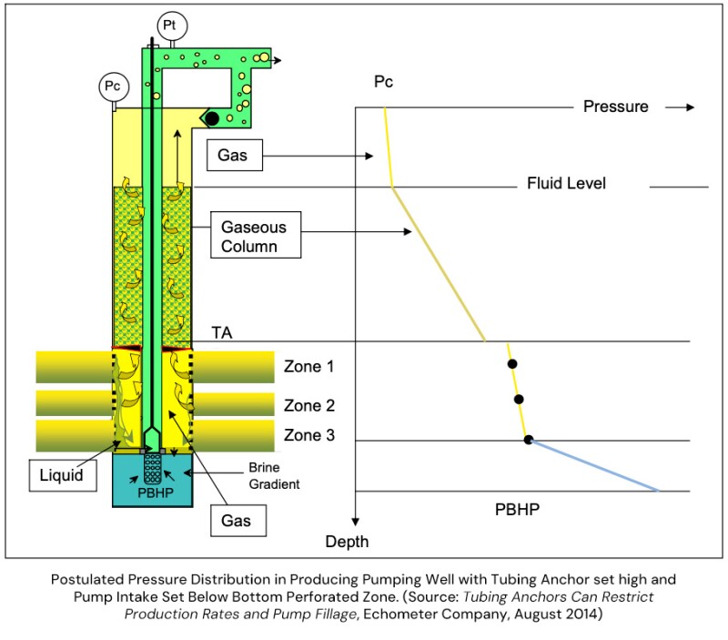
That was the finding of a research study conducted by Echometer Company. The Texas-based software firm offers solutions for analyzing and optimizing the performance of oil, gas and water wells. In this case, the firm studied the production rates of 11 oil wells. Each well had high fluid levels and the pump intake was located below the perforations. Yet despite these seemingly favorable conditions, nine of the wells showed a pump fillage rate of less than 90%.
According to the report: “In these wells that exhibited high fluid levels … the fluid distribution in the wellbore below the liquid level was not uniform. The wellbore in the vicinity of the pump intake was primarily filled with gas with a minimal volume of liquid. …The presence of a tubing anchor set high above the pump intake is considered to be the main cause of this uneven distribution of fluids in the wellbore.
“The particular tubing anchor used in these wells provides a flow area of about 2.9 square inches between the body of the anchor and the casing compared to a flow area of 14.4 square inches between the casing (4.892-in. ID) and the tubing (2.375-in. OD). The small flow area could increase the velocity of the upward flowing gas to the point where it would be difficult for liquid present in the upper part of the annulus to flow downward past the depth where the tubing anchor is set. The anchor would essentially act as a choke and also cause an increase of the annular back pressure.”
In other words, the tubing anchor itself was restricting the flow of gas up through the annulus of the well. The gas that did escape had an increased velocity. That velocity made it difficult for fluid above the anchor to fall past it and reach the pump. In turn, the fluid around the pump had a high gas content, making highly efficient production impossible.
Tubing Anchors Can Provide a "False Positive"
Another key finding in the report was related to the fluid levels in these wells. In many cases, the fluid levels above the anchors appeared higher than they actually were. The report states: “Fluid level depression tests were used to confirm that free gas can collect below a tubing anchor and prevent the liquid present in the gaseous column above the tubing anchor from falling to the bottom of the wellbore and to the pump intake.”
Said differently, the fluid above the anchor was unable to fall past the anchor at a significant enough rate to allow full pump fillage and decrease the overall fluid level. This phenomenon essentially gave operators a false reading, since they thought they had high fluid levels. However, the reality was that fluid just couldn’t get past the anchor as quickly as it was being pumped out.
Two Alternative Design Options
The Echometer report notes that removing the anchor or moving it below the perforations should resolve the issue. Of course, neither option is necessarily ideal. Removing the anchor would increase the flow area within the casing. However, it would also cause the cyclic movement of the tubing string. And although setting the anchor below the perforations can be an effective model with the right equipment, many engineers and field operators are wary of this approach.
Door Number Three: Using a "Slim" Tubing Anchor Catcher
In addition to the report’s suggestions, a third option for mitigating the interference of formation gas does exist: Deploying a tubing anchor catcher with a reduced OD, such as the Slimline® TAC from TechTAC®.
The patented design of the Slimline anchor provides up to 245% more flow-by area, between the anchor and the well casing than a standard B2 TAC. That flow area allows formation gas to more easily flow up around the anchor, while sediment can more easily fall past it.
Using terminology from the Echometer study, while the standard anchor creates a “choke,” causing restrictive turbulent flow, the Slimline, with its tapered design and smaller diameter, allows for a laminar flow path.
Validated by CFD Analysis
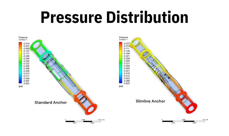
A recent CFD study from the independent consulting firm Imaginationeering confirmed these benefits. The study examined the “gas flow within the annular space around two types of a 5.5-in. tubing anchor catcher to assess the differences between them in terms of flow parameters.” Specifically, the analysis evaluated the performance of a standard B2 tubing anchor catcher and the Slimline TAC relative to fluid velocity, pressure drop, turbulence, vorticity and other factors. The resulting report highlighted two key findings:
Significant Pressure Drop Around the Standard B2 Tubing Anchor Catcher One of the most noteworthy findings of the CFD study dealt with the pressure drop around each anchor. The team at Imaginationeering found that the net pressure drop around a standard B2 tubing anchor catcher, as fluid/gas passes through the annular cavity around the anchor, is more than double the pressure drop around the Slimline TAC.
According to the study: “… the pressure drop along the standard TAC is more than double that drop along the Slimline TAC. This is expected because the annular cavity with the Slimline TAC’s case is wider than that for the standard TAC’s case. Furthermore, the pressure drop change in the Slimline TAC’s case is less abrupt than that in the standard TAC’s case in which a noticeable localized drop prior to the downstream connector is observed.”
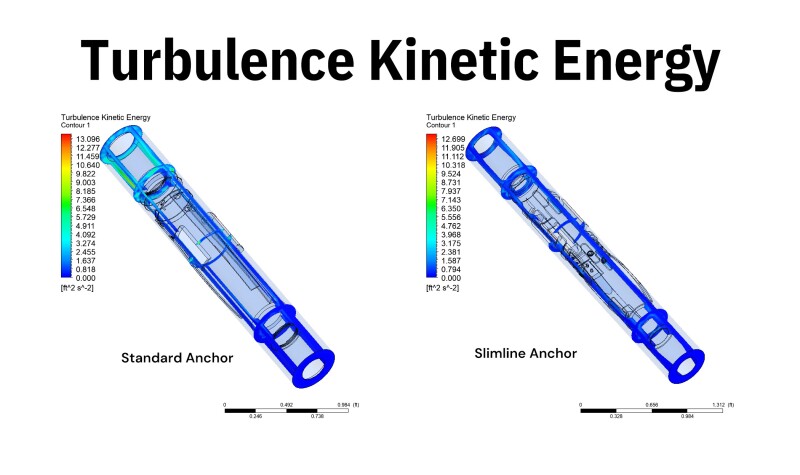
Less Turbulence and Vorticity Around the Slimline TAC
The Slimline anchor also demonstrated a noticeable advantage over the standard B2 tubing anchor catcher in reducing the overall turbulence and vorticity strengths within the flow field.
The report noted, “The observed abrupt changes in the pressure field along with the potential presence of flow field obstacles in the case of the standard TAC is expected to generate more turbulence within the flow field along the TAC in comparison with the Slimline TAC’s case … Further, the vorticity strength in the flow field of the Standard TAC is expected to be significantly present in comparison to that of the Slimline TAC’s case …”
The Impact of the CFD Study Findings
The significant pressure drop and increased turbulence and vorticity as fluid passes around the standard B2 TAC can have a material impact on well production. Those parameters are major contributors in the formation of scale, iron sulfide, and paraffin, as well as the advent of gas locking.
In contrast, the CFD study highlights multiple benefits of running the TechTAC Slimline anchor:
By reducing the pressure and temperature drop as fluid passes around the anchor, as well as the resulting turbidity and turbulence of the fluid itself, the Slimline TAC significantly diminishes the formation of scale, iron sulfide, paraffin, and solids.
In reducing the formation of those solids, the Slimline TAC is much less susceptible to plugging, where sediment bridges off on top of the anchor and traps formation gas below it.
When formation gas is not trapped below the TAC or jettisoned at high speeds around the anchor, operators can significantly reduce one of the most significant issues impacting production in the oil field: the gas locking of a rod pump.
Conclusion
Gas locking is a common and challenging issue in the oil field—one that can have significant consequences for production rates and operating costs. Understanding the causes and consequences of gas locking is essential for oil producers to implement effective mitigation strategies.
One of the most cost-effective ways to mitigate gas locking in sucker rod pump (SRP) systems is by deploying a Slimline TAC from TechTAC. The Slimline’s unique design dramatically increases flow-by capacity, which reduces the occurrence of gas locking by directing gas around the anchor instead of through the pump. By minimizing the frequency and impact of gas locking, production companies can significantly reduce costs, increase run time, and increase the production of oil well operations.