SevKomNefteGaz LLC
P. Likhachev — LikhachevPA@skn.rosneft.ru
B. Khusainov — BI_Khusainov@skn.rosneft.ru
P. Leontiev — PV_Leontev2@skn.rosneft.ru
WORMHOLES R&D LLC
O. Zhuravlev — ozhuravlev@wormholes.ru
A. Gribanov — agribanov@wormholes.ru
A. Suvorov — asuvorov@wormholes.ru
The efficiency of developing oil and gas fields is largely determined by the magnitude of the costs associated with hydrocarbon production. Current industry trends indicate that the companies that succeed are those that actively implement technological solutions aimed at reducing production costs and increasing the efficiency of production processes. Under conditions of high competition, technological modernization is no longer an additional advantage — it has become a necessary condition for sustainable development and market stability.
One of the most significant achievements of recent decades in the field of drilling has been the widespread adoption of horizontal wells, which allow for a significant increase in reservoir recovery. However, the increase in the length of the productive borehole has led to the emergence of new challenges, primarily the need for detailed and reliable monitoring of the fluid phase distribution along the wellbore. The use of traditional geophysical methods, particularly systems based on coiled tubing or downhole tractor devices, is associated with several limitations. Among these are high hydraulic losses, distortion of the natural inflow, limited depth of descent, and a high probability of complications during operations.
As part of addressing these challenges, SevKomNefteGaz implemented and tested a reusable retrievable system based on marker technologies. The application of this system enabled the acquisition of quantitative characteristics of inflow distribution along the horizontal wellbore without interfering with the operating mode of the well. This not only reduced time and financial costs but also improved the accuracy of productivity forecasting, which directly influences the strategy for further field development.
In collaboration with WORMHOLES R&D, a project was carried out to operate the retrievable marker system (see Figure 1) at the Severo-Komsomolskoye field. The system, based on solutions previously implemented in more than a hundred wells, provides for the installation of monitoring modules at various intervals of the productive formation. This makes it possible to construct a detailed picture of the inflow profile and to identify zones of oil and water inflow, which allows for subsequent adjustments to the development regime.

Figure 1. Device for Interval Inflow Monitoring
The operation of the system is ensured through the use of active markers that react upon contact with oil or water. These components release tracers that are detected in the collected samples. Sequential sampling of formation fluid at the wellhead and its subsequent laboratory analysis make it possible to accurately assess the contribution of individual zones to the total production rate, without disrupting the established equipment operating mode. This approach eliminates the data distortion typical of traditional methods and makes monitoring more reliable and economically justified.
As part of the pilot project, the work was carried out in two stages. During the first stage, a deployment of the assembly with marker cassettes was performed in the horizontal section of the well. The second stage included systematic sampling at the wellhead and analysis of the samples at the laboratory of WORMHOLES R&D. Sampling was carried out after the well reached its operational mode.
An improved marker system for distributed inflow profile monitoring was applied to one of the horizontal wells. The equipment was installed on 73-mm diameter tubing and fixed in the horizontal section of the 114-mm diameter production well. The well design included fifteen packers, forming eight productive intervals. For the current analysis of the inflow profile, monitoring modules were used, evenly distributed across four key intervals, each covering several inflow zones. After deployment to the planned depth, the assembly was disconnected using a standard hydraulic disconnector.
One of the key engineering challenges encountered during implementation was the high likelihood of equipment silting, associated with the presence of abrasive inclusions in the well’s production. An additional risk was posed by the extended configuration of the assembly in the horizontal section of the wellbore, especially during prolonged operation without retrieval. This justified the decision to abandon the use of packers in the new version of the system. The modified assembly provided for fluid circulation in the annular space between the tubing and the tailpipe, while preventing fluid ingress inside the tubing through the installation of a blind shoe in the bottom part. The flow moved from the bottomhole to the wellhead, allowing each interval to be individually marked. To stabilize the hydrodynamics, additional turbulence-generating elements were integrated with the measuring modules.
After installation was completed, an electric submersible pump was installed in the well, and the facility was put into operational mode. After one week of stabilized production rate, wellhead sampling began — for five days, fluid samples were collected twice a day and sent for laboratory analysis to determine marker concentrations.
The key advantages of the implemented approach include:
Reduction of technological risks: the abandonment of packers and the circulation scheme ensured stable operation without blockage.
Improved monitoring reliability: the markers made it possible to determine the quantitative inflow of oil and water.
Maintenance of the operating mode: continuous sampling eliminated the need to shut down the well, preserving natural operating conditions.
Flexibility and adaptability: adjustment of the sampling schedule made it possible to account for the dynamics of inflow and improve interpretation accuracy.
The system demonstrated efficiency under conditions of high mineralization of the production and increased content of mechanical impurities. Compatibility with the existing infrastructure (in particular, with 73-mm tubing and electric submersible pumps) confirms its applicability in mature and watered-out fields. The data obtained formed the basis for subsequent geological and technical analysis and the development of water shutoff solutions.
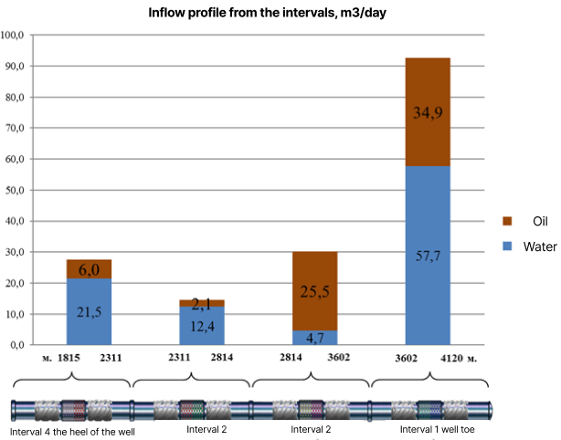
Figure 2. Inflow Profile from Intervals, m³/day
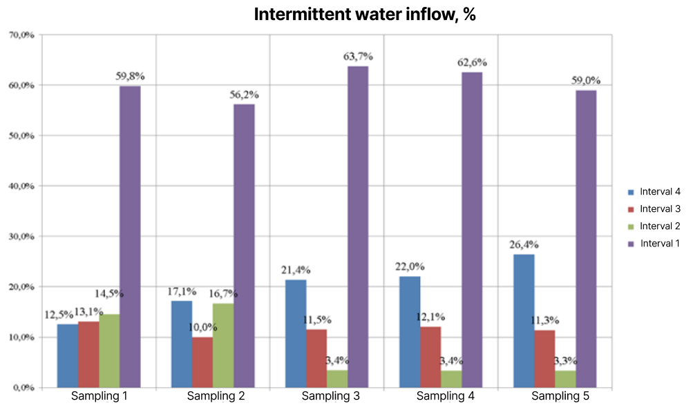
Figure 3. Interval Water Inflow, %
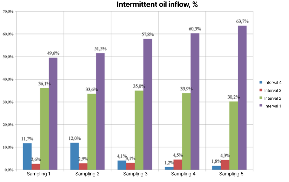
Figure 4. Interval Oil Inflow, %
Laboratory studies (Figures 2, 3, and 4) revealed significant heterogeneity in the profile: in the interval at the bottomhole, the main water inflow was recorded — 57.7 m³/day of water and 34.9 m³/day of oil, accounting for almost 60% of the total volume; whereas at the wellhead, the values were 21.5 m³/day of water and 6.0 m³/day of oil.
Isolation modelling revealed the following:
Isolation of the lower interval reduced water cut by 2.5%, but was accompanied by a loss of 66.2 m³/day of oil.
Isolation at the wellhead provided a reduction in water cut by 3.9% with a loss of 32.9 m³/day of oil.
Comprehensive isolation of both intervals and bridging of the lower section as a result of sand production provided a total reduction in water cut by 16.1%, but was accompanied by a decline in total production rate of 120.2 m³/day of fluid and 70.6 m³/day of oil.
These results emphasize the need for a strategic approach to water cut management, focusing not only on reducing water inflow but also on maintaining acceptable levels of oil production. Thus, isolation of the zone in interval No. 4 proved to be more preferable in terms of the ratio of water cut reduction to oil loss.
Upon completion of the monitoring, the assembly was successfully retrieved in accordance with the approved plan. The results of the inspection confirmed the technical integrity of all components, which allows the equipment to be reused without additional costs for restoration.
Thus, the presented method combines technological novelty with high practical value, providing an accurate assessment of the inflow profile, a reduction in silting risks, and rapid integration into existing technological processes. Its application contributes to more informed decision-making in conditions of increasing water cut and the complication of geological and production conditions.